Solar pumping system introduction
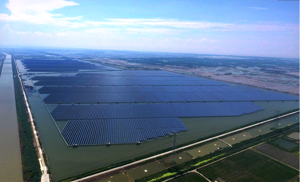
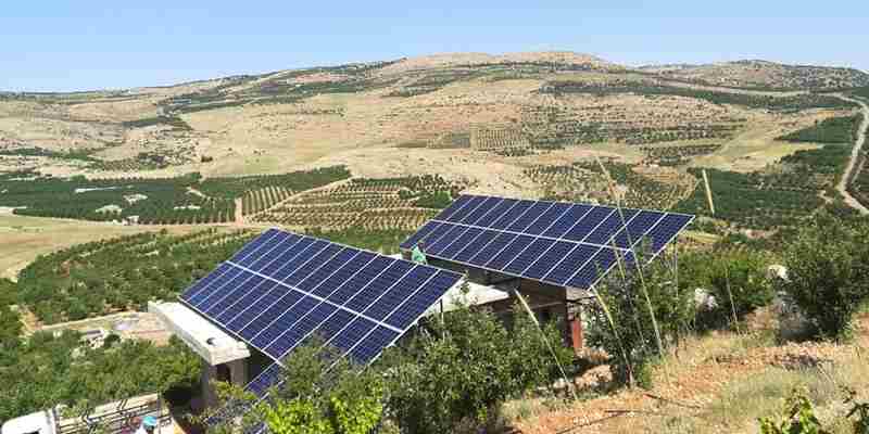
Solar pumping systems can be applied to all forms of daily use, water pumping for drinking water supply for remote villages and farms without connection to the water grid, for agricultural use such as livestock watering, agricultural irrigation, forestry irrigation, pond management, desert control, and industrial use such as waste water treatment etc.
In recent years, with the promotion of the utilization of renewable energy resources, solar pumping systems are more and more used in municipal engineering, city center squares, parks, tourist sites, resorts and hotels, and fountain systems in residential areas.
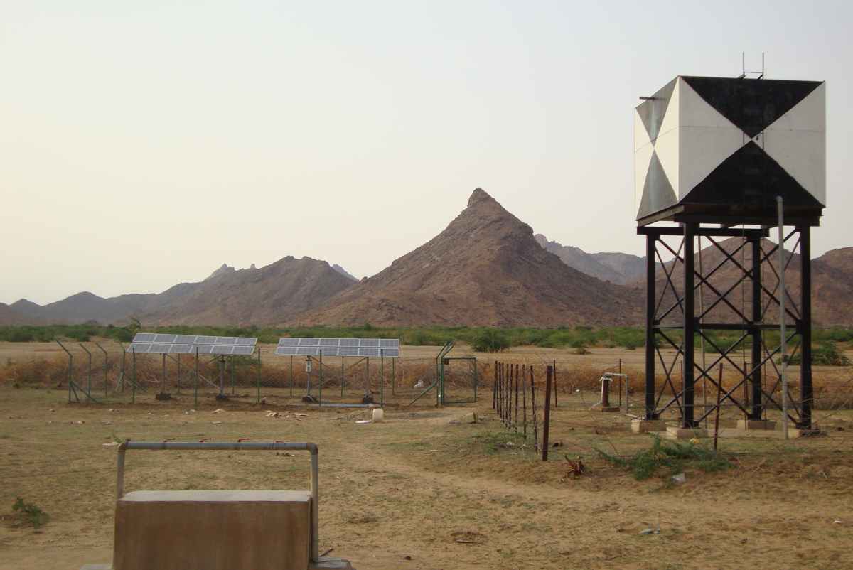
The system is composed of a PV generator ( solar panels ), a pump and a solar pump inverter. Based on the design philosophy that it is more efficient to store water rather than electricity, there is no energy storing device such as storage battery in the system. The system is prepared to be combined with a elevated water storage, e.g. water tower or an uphill tank installation.
The PV generator, an aggregation of PV modules connected in series and in parallel, absorbs solar irradiation and converts it into electrical energy, providing power for the whole system. The pump inverter controls and adjusts the system operation and converts the DC produced by the PV module into AC to drive the pump, and adjusts the output frequency in real-time according to the variation of sunlight intensity to realize the maximum power point tracking (MPPT). The pump, driven by 3-phase AC motor, can draw water from deep wells, rivers and lakes and pour it into storage tanks or reservoirs, or be connected directly to the irrigation system, fountain system, etc. According to the actual system demand and installation condition, different types of pumps such as centrifugal pump, axial flow pump, mixed flow pump or deep well pump can be used.

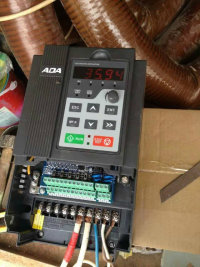
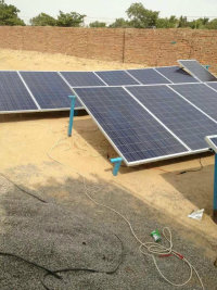

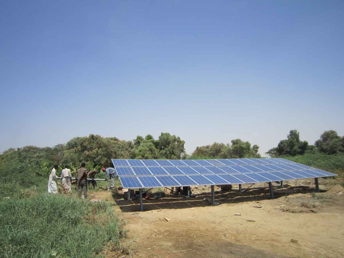

Solar pump system constitution.
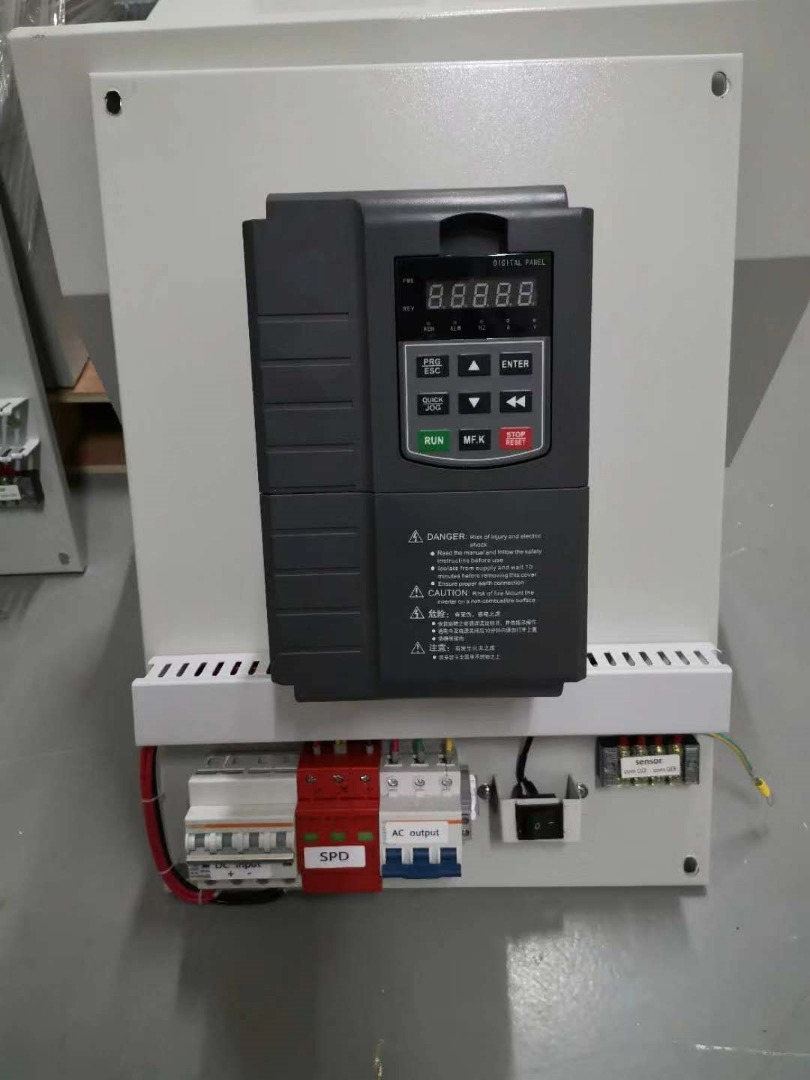
.Solar pump system include solar panels arrays, solar pump inverter and AC 1/3 phase pumps, and other accessories, such as combiner box, DC circuit breaker, AC/DC manual switchover, AC circuit breaker....
System wiring diagram including solar panels, solar pump inverter and pumps.
² High flow system for faster tank fill and significant water output with MPPT function.
² ·Proven motor and pump technology for long-term reliability
² ·Available free of cost at your doorstep, one times investment for more than 20 years free using
² ·Clean and pollution free energy, eco-friendly.
² ·Ideal for remote areas, where electricity is not available or availability is capital intensive.
² ·Suitable for day time irrigation, continuous supply for 8-12 hours in a day.
² ·Soft start feature prevents water hammer and increases system life easy to operate.
² ·Simple installation and maintenance free.
Solar pump inverter operation theory
The solar pump inverter uses the maximum power point tracking (MPPT) control program to improve the efficiency of solar energy systems. The output of the photovoltaic (PV) cell is proportional to its area and intensity, while the output voltage is limited by P-N junction from 0.6 to 0.7 V. Therefore when the output voltage is constant, output power is proportional to intensity and surface area. The current and voltage at which the PV cell generates maximum power is known as the maximum power point.
The MPPT controller follows different strategies to derive the maximum power from the PV array. The internal MPPT algorithm is used to derive maximum power from the PV cell at any instant. This is achieved by modifying the operating voltage or current in the PV cell until the maximum power is obtained.
When the output voltage is zero, the PV cells create short circuit current. If the PV cells are not connected to any load, the output voltage is equal to the open circuit voltage. The maximum power point is obtained at the knee of the I-V curve. See the I-V characteristics shown below.
The I-V curve is not constant since intensity and temperature changes during day time. Under constant temperature, current changes linearly with intensity and voltage changes logarithmically with intensity. Since the voltage variation is small with respect to intensity changes, maximum power varies proportionally with intensity
Chapter2. PV serial solar pump inverter selection
2.1 PV series solar pump inverter nameplate.
2T models:It uses for 220VAC pumps, 150VDC to 450VDC input, recommend 310Vmp.
(Lowest 80VDC input is option)
4T models:It uses for 380VAC pumps, 350VDC to 800VDC input, recommend 540Vmp.
( 250VDC input is option)
5T models: it uses for 480VAC pumps, 350VDC to 900VDC, recommend 676vmp.
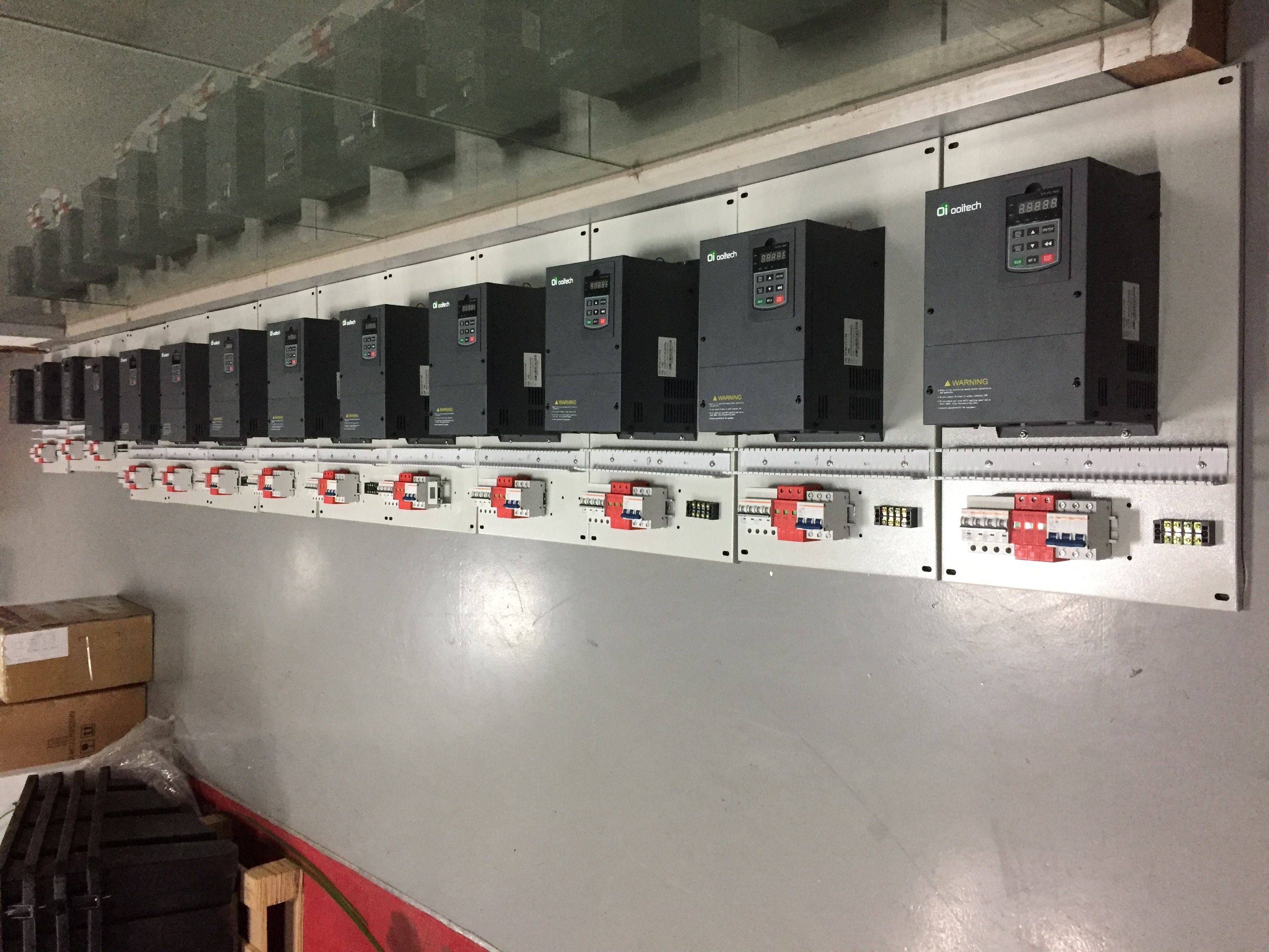
2.2. PV350/PV800 solar Pump inverter models list:
Model | Input voltage | Output for pumps | Power |
PV350-2T | 150 to 450VDC, or 220VAC | 3 PH 0-220VAC | 0.4kw/0.75kw/1.5kw/2.2kw |
PV800-2T | 150 to 450VDC, or 220VAC | 3 PH 0-220VAC | 0.75kw to 75kw |
PSD350-2T | 150 to 450VDC, or 220VAC | 3 PH 0-220VAC | 0.4kw/0.75kw/1.5kw/2.2kw |
PSD800-2T | 150 to 450VDC, or 220VAC | 3 PH 0-220VAC | 0.75kw-18.0kw |
PV350-4T | 250 to 800VDC 380VAC/415VAC | 3 PH 0-380/415VAC | 0.75kw—3.7kw |
PV800-4T | 250 to 800VDC 380VAC/415VAC | 3 PH 0-380/415VAC | 0.75kw—500kw |
PSD350-4T | 250 to 800VDC 380VAC/415VAC | 3 PH 0-380/415VAC | 0.75kw—3.7kw |
PSD800-4T | 250 to 800VDC 380VAC/415VAC | 3 PH 0-380/415VAC | 0.75kw—30kw |
2.3. PV350/800 serial solar pump inverter model list |
|
|
|
|
|
|
|
|
|
|
SN | Models | Rate current | Output voltage ( 3PH VAC) | Applicable for pumps | Packing size | MPPT voltage (VDC) | GW Kgs |
|
|
|
2T series : 150 to 450 VDC or 220VAC input, Vmp 310VDC, 372VDC |
|
|
|
|
|
|
|
|
|
|
1 | PV350-2T0.75GB | 4A | 0 – 220V | 0.75KW | 215*170*190 | 260 to 355 | 1.5 |
|
|
|
2 | PV350-2T1.5GB | 7A | 0 -220V | 1.5KW | 215*170*190 | 260 to 355 | 1.5 |
|
|
|
3 | PV350-2T2.2GB | 10A | 0 -220V | 2.2kw | 215*170*190 | 260 to 355 | 1.5 |
|
|
|
4 | PV800-2T3.7G | 16A | 0 -220V | 3.7kw | 280*180*215 | 260 to 355 | 1.5 |
|
|
|
5 | PV800-2TXXGB | ** | 0-220V | <75kw | No-standard | 260 to 355 | ** |
|
|
|
4T series, 250/ 350 to 800 VDC or 380VAC, Vmp540VDC, Voc 648VDC |
|
|
|
|
|
|
|
|
|
|
4 | PV350-4T0.75GB | 2.5A | 0-440V | 0.75KW | 215*170*190 | 486 to 650 | 1.5 |
|
|
|
5 | PV350-4T1.5GB | 3.7A | 0-440V | 1.5KW | 215*170*190 | 486 to 650 | 1.5 |
|
|
|
6 | PV350-4T2.2GB | 5A | 0-440V | 2.2KW | 215*170*190 | 486 to 650 | 1.5 |
|
|
|
7 | PV350-4T3.7GB | 10A | 0-440V | 3.7KW | 215*170*190 | 486 to 650 | 1.5 |
|
|
|
8 | PV800-4T1.5GB | 3.7A | 0-440V | 1.5KW | 280*180*215 | 486 to 650 | 3 |
|
|
|
9 | PV800-4T2.2GB | 5A | 0-440V | 2.2KW | 280*180*215 | 486 to 650 | 3 |
|
|
|
10 | PV800-4T3.7GB | 10A | 0-440V | 4.0KW | 280*180*215 | 486 to 650 | 3 |
|
|
|
11 | PV800-4T5.5GB | 13A | 0-440V | 5.5KW | 320*215*250 | 486 to 650 | 4.3 |
|
|
|
12 | PV800-4T7.5GB | 17A | 0-440V | 7.5KW | 320*215*250 | 486 to 650 | 4.5 |
|
|
|
13 | PV800-4T11GB | 25A | 0-440V | 11KW | 390*275*285 | 486 to 650 | 6.5 |
|
|
|
14 | PV800-4T15GB | 32A | 0-440V | 15KW | 390*275*285 | 486 to 650 | 6.6 |
|
|
|
15 | PV800-4T18.5GB | 38A | 0-440V | 18.5KW | 445*205*315 | 486 to 650 | 12 |
|
|
|
16 | PV800-4T22GB | 45A | 0-440V | 22KW | 445*205*315 | 486 to 650 | 12 |
|
|
|
17 | PV800-4T30G | 60A | 0-440V | 30KW | 545*395*370 | 486 to 650 | 16 |
|
|
|
18 | PV800-4T37G | 75A | 0-440V | 37KW | 660*420*415 | 486 to 650 | 16 |
|
|
|
19 | PV800-4T45G | 90A | 0-440V | 45KW | 660*420*415 | 486 to 650 | 27 |
|
|
|
20 | PV800-4T55G | 110A | 0-440V | 55KW | 700*480*410 | 486 to 650 | 35 |
|
|
|
21 | PV800-4T75G | 150A | 0-440V | 75KW | 700*480*410 | 486 to 650 | 35 |
|
|
|
22 | PV800-4T93G | 170A | 0-440V | 93KW | 700*480*490 | 486 to 650 | 53 |
|
|
|
23 | PV800-4T110G | 210A | 0-440V | 110KW | 700*480*490 | 486 to 650 | 56 |
|
|
|
25 | PV800-4T132G | 260A | 0-440V | 132KW | 780*540*510 | 486 to 650 | 71 |
|
|
|
25 | PV800-4T160G | 300A | 0-440V | 160KW | 780*540*510 | 486 to 650 | 72 |
|
|
|
26 | PV800-4T185G | 340A | 0-440V | 185KW | 1130*580*570 | 486 to 650 | 149 |
|
|
|
27 | PV800-4T200G | 380A | 0-440V | 200KW | 1130*580*570 | 486 to 650 | 180 |
|
|
|
PSD350 IP54, 2T series, 150 to 450 VDC or 220VAC input, Vmp 310VDC, 372VDC |
|
|
|
|
|
|
|
|
|
|
1 | PSD350-2T0.75GB | 4A | 0-220V | 0.75KW | 265*180*210 | 260 to 355 | 2 |
|
|
|
2 | PSD350-2T1.5GB | 7A | 0-220V | 1.5KW | 265*180*210 | 260 to 355 | 2 |
|
|
|
3 | PSD350-2T2.2GB | 10A | 0-220V | 2.2kw | 265*180*210 | 260 to 375 | 2 |
|
|
|
4 | PSD800-2T3.7GB | 16A | 0-220V | 3.7kw | 335*225*245 | 260 to 355 | 3 |
|
|
|
PSD800 IP54, 4T series, 250 to 800 VDC or 380VAC, Vmp540VDC, Voc 648VDC |
|
|
|
|
|
|
|
|
|
|
4 | PSD350-4T0.75GB | 2.5A | 0-440V | 0.75KW | 265*180*210 | 486 to 650 | 2 |
|
|
|
5 | PSD350-4T1.5GB | 3.7A | 0-440V | 1.5KW | 265*180*210 | 486 to 650 | 2 |
|
|
|
6 | PSD350-4T2.2GB | 5A | 0-440V | 2.2KW | 265*180*210 | 486 to 650 | 2 |
|
|
|
7 | PSD350-4T3.7GB | 10A | 0-440V | 3.7KW | 265*180*210 | 486 to 650 | 2 |
|
|
|
8 | PSD800-4T5.5GB | 13A | 0-440V | 5.5KW | 400*270*290 | 486 to 650 | 4.3 |
|
|
|
9 | PSD800-4T7.5GB | 16A | 0-440V | 7.5KW | 400*270*290 | 486 to 650 | 4.5 |
|
|
|
10 | PSD800-4T11GB | 25A | 0-440V | 11KW | 440*330*310 | 486 to 650 | 6.5 |
|
|
|
11 | PSD800-4T15GB | 32A | 0-440V | 15KW | 440*330*310 | 486 to 650 | 7 |
|
|
|
12 | PSD800-4T18.5G | 38A | 0-440V | 18.5KW | 540*400*365 | 486 to 650 | 10 |
|
|
|
13 | PSD800-4T22GB | 45A | 0-440V | 22KW | 540*400*365 | 486 to 650 | 11 |
|
|
|
14 | PSD800-4T30G | 60A | 0-440V | 30KW | 540*400*365 | 486 to 650 | 14 |
|
|
|
|
|
|
|
|
|
|
|
|
|
|
Chapter3. PV series solar pump inverter specification.
** Specification of Solar pump inverter specification when parameters H9.00 set to for 1. |
|
Recommended MPPT voltage range | Vmp 260 to 355VDC for 2T ( For driving 220VAC pumps ) Vmp 486 to 650 VDC for 4T (For driving 380VAC pumps) |
Recommended input Voc and Vmpp voltage | Voc 355(VDC), Vmpp 310(VDC) for 2T model or 220V AC pumps Voc 620(VDC), Vmpp 540(VDC) for 4T model or 380V AC pumps |
Motor(pump) type | Control for permanent magnet synchronous motor (PMSM )and asynchronous motor pumps ( all type 3 phase induction motor) |
Rated output voltage | 3-Phase,110V/160V/220V. 3-phase, 220V/380V/460V |
Output frequency range | 0~Maximum frequency 400Hz. |
Efficiency | 99.2 to 99.6% |
Over load capacity | G type for submersible pumps, 150% rated current for 60s, 180% rated current for 3s P type for surface pump, 120% rated current for 60s, 150% rated current for 2s. |
Solar pump control special performance | MPPT ( maximum power point tracking),auto/manual operation, dry run protection, low stop frequency protection, minimum power input, motor maximum current protection, flow calculating, energy generated calculating and water tank level detected. |
Protection function | Phase loss protection, phase short circuit protection, ground to phase circuit protection , input and output short circuit protection. Stall protection, lightning protection, over heat protection. |
Protection degree | IP20, Air force cooling |
Running mode | MPPT or CVT |
Altitude | Below 1000m; above 1000m, derated 1% for every additional 100m. |
Standard AC input backup circuit | CE, Design based on AD800 series high performance inverter, more specification please refer to AD800 series vector control inverter operation manual |
Specification of frequency inverter when H9.00=0 for motor VFD.
H9.00=1, It works as solar pump controller with MPPT, H9.00=0, it works as VFD when AC grid |
|
|
|
|
Control mode | Control mode | SVC in open loop | V/F control | Close loop vector control* |
Starting torque | 0.5Hz 180% | 0.5Hz 150% | 0.00Hz 180%* |
|
Speed adjust range | 1:100 | 1:100 | 1:1000* |
|
Speed stabilizing precision |
|
| ±0.02%* |
|
Torque precision | NO | NO | ±5% |
|
Motor type | General induction motor, Permanent magnet synchronous motor (PMSM )* |
|
|
|
Function design | Highest frequency | General vector control :400Hz V/f control:4000Hz |
|
|
Frequency resolution | Digital setting: 0.01Hz analog setting:maximum×0.025% |
|
|
|
Carrier frequency | 0.5K~16KHz, the carrier frequency can be adjusted by temperature automatically |
|
|
|
Frequency reference setting method | Digital of Control panel, analog AI1, AI2, potentiometer of control panel, UP/DN control, communication, PLC pulse frequency |
|
|
|
Acceleration./deceleration characteristic | Linear curve and S curve accel. /decel. mode, range of time: 0.0 to 65000S. |
|
|
|
V/F curve | 3 mode: linear, multiple points, N Power |
|
|
|
V/F separation | 2 times separation: totally separation, half separation |
|
|
|
DC braking | DC braking frequency: 0.0 to 300Hz, DC braking current: 0.0% to 100% |
|
|
|
Braking unit | Standard built in for up to 4T22GB(22kw), optional built it for 4T37G~4T75G (18.5kw to 75kw), external built for above 4T93G (95kw). |
|
|
|
Jog function | JOB frequency range: 0.0 to 50.0Hz, the acceleration and deceleration time of Jog |
|
|
|
Configured PID function | Easy to perform pressure, flow, temperature close loop control. |
|
|
|
PLC multiple speed | To achieve 16 segment speed running through built in PLC or terminal control |
|
|
|
Common Dc bus | Multiple inverters use one DC bus for energy balance. |
|
|
|
Auto voltage regulation (AVR) | Enable to keep output voltage constant when grid fluctuation |
|
|
|
Over load tolerance capability | G type model: 150% rated current for 60s, 180% rated current for 3s, P type Model: 120% rated current for 60s, 150% rated current for 3s. |
|
|
|
| Stall protection control when over current, over voltage | Carry out limiting automation for running current, voltage to prevent over current, over voltage frequently |
|
|
Rapid current limit function | Minimize the IGBT module broken to protect the AC inverter, maximum reduce the over current fault. |
|
|
|
Torque limit and torque control | "Excavator" characteristics , torque limit automatically during motor running. Torque control is available in close loop vector control mode. |
|
|
|
Features | Friendly interface | Display Hello when power on. |
|
|
Multiple function key JOG button | It can set for Forward Jog, reverse Jog, forward/reverse switch |
|
|
|
Timing control function | A total running time and total running time calculating |
|
|
|
2 group motor parameters | To achieve two motor switchover freely, control mode is selectable |
|
|
|
Motor over heat protection | Accepting motor temperature sensor signal input via AI1 terminals. |
|
|
|
Multiple kinds encoder * | Compatible collector PG, differential PG, and rotary transformer Encoder( resolver). |
|
|
|
Command source | Control panel, control terminals, series communication, switch freely. |
|
|
|
Frequency source | Digital setting, analog current/voltage, pulse setting, serial communication, main and auxiliary combination. |
|
|
|
Protection function | Short circuit detect when power on, input/output phase loss, over voltage, over current, under voltage, over heat, over load protection. |
|
|
|
Environment | Application site | Indoor, free of exposure to sunlight, no dusty, no corrosive, no inflammable gas, no oil and water vapor, and water dipping |
|
|
Altitude | Lower 1000m |
|
|
|
environment temperature | -10℃~+40℃, power derated for 40~50℃, rated current derated 1% for 1℃ increasing. |
|
|
|
humidity | Less than 95%, no water condense. |
|
|
|
![]()
![]()


